
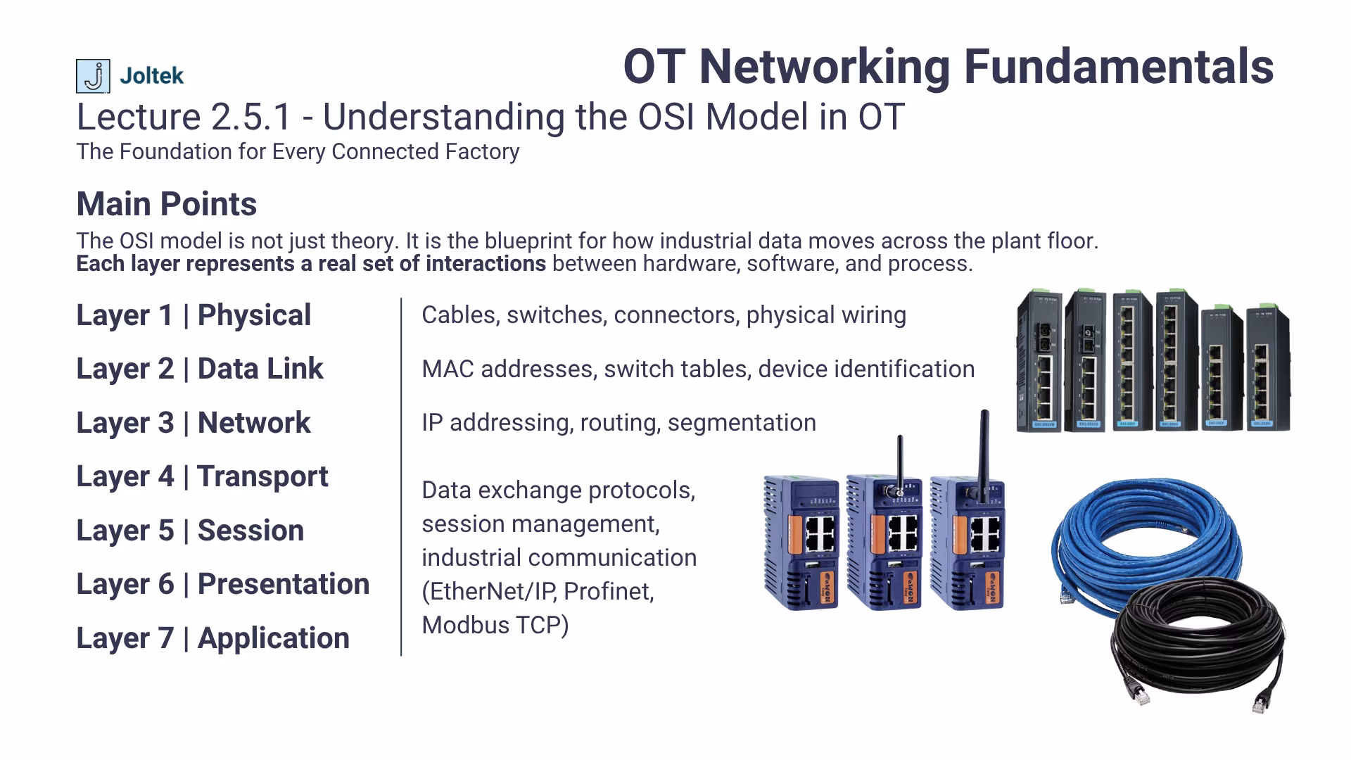
The OSI model is often described as a theoretical framework, but on the plant floor it becomes an everyday reality. In manufacturing, data does not simply travel across clean data centers or office networks. It moves through panels filled with control hardware, through cables routed beside high voltage lines, and through switches that must operate in high temperature and high vibration environments. Understanding how these seven layers interact is not just academic knowledge. It is what allows engineers to diagnose, design, and maintain communication systems that keep production running.
For many in Information Technology, the OSI model serves as a reference for protocol design and data flow visualization. For those in Operational Technology, it defines the boundaries between hardware, firmware, and control logic. Every time a PLC loses communication with an HMI, or a drive stops responding to a command, the process of troubleshooting inevitably moves through these layers one by one. It starts with checking the physical cable connection and ends with verifying that the correct data is being exchanged between applications such as SCADA or MES.
The importance of this framework extends beyond troubleshooting. It establishes a shared language that bridges the work of IT and OT professionals. When a technician reports a layer one issue, they are referring to the physical infrastructure. When an IT specialist mentions a layer three conflict, they are referencing routing or IP address configuration. Developing this shared understanding allows teams to align faster, reduce downtime, and eliminate confusion across disciplines.
In this post, we connect each layer of the OSI model to its real world equivalent on the plant floor. We look at what physical layer failures actually look like inside a control cabinet, how data link and network layers determine visibility between systems, and how the upper layers translate to the protocols that carry production data. This perspective moves away from theory and focuses on what truly matters to the reliability of your automation systems.
For readers looking to expand their understanding of how network architecture influences system reliability, visit Joltek’s IT and OT Architecture Integration page.
Every reliable industrial network begins with the physical layer. It may sound simple, but this is where most communication problems originate. In an operational environment filled with heavy equipment, variable power loads, and electromagnetic interference, even a single cable can determine whether production runs smoothly or grinds to a halt. Every network issue starts with a physical layer check.
Unlike climate-controlled offices or IT data centers, industrial environments constantly challenge network hardware. Equipment operates near motors, drives, and power panels that emit electrical noise. Humidity, vibration, and dust can degrade insulation and loosen connectors. Over time, even small imperfections in a cable or termination can result in intermittent communication faults that are extremely difficult to trace.
This is why the physical layer must never be treated as an afterthought. On the plant floor, a technician’s ability to diagnose and correct a physical issue quickly can save hours of downtime and thousands of dollars in lost production. When communication problems appear sporadic, it is often because environmental factors have affected the integrity of the cable rather than the logic or configuration.
While every facility is different, certain problems appear again and again across industries. Recognizing them helps narrow the scope of troubleshooting before diving into software or logic:
Each of these issues directly affects data reliability. When devices such as PLCs, HMIs, and drives experience packet loss or irregular updates, operators often suspect programming errors. In reality, most of these failures originate at the very first layer of the OSI model.
A disciplined approach to physical layer design and maintenance ensures long term reliability. The following practices form the foundation of any well designed industrial network:
Attention to these fundamentals not only improves performance but also strengthens cybersecurity by reducing unexpected disconnections and rogue network reconnections during maintenance. The most effective integration work always begins at this level. To understand how field technicians and engineers diagnose and resolve such foundational issues, visit Joltek Systems Integration and Field Support which outlines how structured integration practices improve reliability across control systems.
The second layer of the OSI model is where devices begin to take on individuality within a network. It governs how they recognize one another and how data is framed and transferred between nodes. While often overlooked in industrial environments, understanding this layer is essential for building reliable systems and troubleshooting complex communication problems. The MAC address is the digital fingerprint of your hardware.
Every industrial device, whether it is a PLC, VFD, IPC, or remote I/O module, has a unique MAC address that is permanently assigned by the manufacturer. This address is written directly into the hardware and cannot be changed. It serves as the lowest level of identity for a device on an Ethernet network. When a packet travels through switches, the MAC address determines where it should be sent and how traffic should be handled.
In an OT environment, this concept becomes even more critical. A plant floor can contain hundreds of similar devices manufactured by the same vendor. Without clear documentation of MAC addresses, tracking which piece of equipment corresponds to which port becomes a guessing game. When a system integrator or maintenance technician replaces a drive or controller, knowing its MAC address helps confirm that the network has recognized it correctly and that there are no conflicts with existing devices.
In practice, the data link layer often reveals its importance when hardware is replaced during maintenance or system upgrades. Consider a scenario where two identical PLCs are swapped without updating device mappings on the managed switch. Both may temporarily share similar configurations, and if the old MAC address remains cached in the switch’s table, the network can misdirect traffic. The result is unstable communication, intermittent disconnections, or broadcast storms that appear random at first glance.
Proper documentation and verification of MAC addresses prevent these costly issues. When engineers label devices clearly, maintain updated network records, and verify switch tables after replacements, they ensure consistent communication between all components. It may seem procedural, but this level of discipline distinguishes a well-managed network from one that causes recurring downtime.
When communication issues arise at the data link layer, several tools and techniques can help isolate the problem efficiently:
A deep understanding of the data link layer transforms troubleshooting from guesswork into a structured process. Instead of reacting to intermittent network behavior, technicians can pinpoint root causes by following the digital trail left by each device.
For readers who want to explore this topic in greater detail, including examples of how MAC addresses interact with switches and controllers in industrial environments, visit Understanding MAC Addresses in OT Networks.
At this stage of the OSI model, communication starts to take form. The network layer introduces structure, organization, and logic to how data moves between systems. In a manufacturing environment filled with PLCs, HMIs, drives, and servers, this structure determines whether devices can talk to each other reliably and whether a fault stays contained or cascades across the entire plant network. Without proper IP planning, even well built networks fail.
Layer three defines how each device communicates by assigning unique IP addresses. Every PLC, HMI, or industrial PC on a network must have its own address within a specific subnet so that data packets know exactly where to go. Think of this as assigning street numbers within a neighborhood. Without unique identifiers, deliveries (or in this case, data packets) would be lost or misdirected.
In manufacturing, static addressing is almost always preferred. Devices in an operational environment are expected to run for years with minimal reconfiguration. If an IP address changes unexpectedly, it can break connections between systems such as SCADA, MES, or historian platforms. Static IP assignments ensure that once an address is configured, it stays consistent across power cycles, hardware replacements, and software updates.
This stability is critical in systems that operate twenty four hours a day. When production depends on real time communication, every second of lost connectivity translates into downtime, rejected product, or lost visibility. A consistent addressing scheme allows maintenance teams to locate devices quickly and ensures that backups, alarms, and control signals always reach the right destination.
Even when networks are built with the right equipment, poor IP planning often leads to recurring problems. Some of the most common challenges include:
Each of these issues points to the same root cause: a lack of structure. By applying clear IP management practices, facilities can isolate problems more effectively, improve network performance, and reduce the impact of human error during system changes.
Subnets are what bring order to large networks. They define which devices can communicate directly and which ones must pass through a router or managed switch to reach each other. In operational technology, this segmentation is not just about organization. It is a key part of performance optimization and cybersecurity.
For example, a plant might divide its network as follows:
By isolating each area, traffic remains local to that part of the process. A broadcast from a machine in packaging will not affect a drive in utilities. This separation simplifies troubleshooting, improves data flow, and makes it easier to implement cybersecurity measures such as firewalls or VLANs.
A well planned subnet structure also creates a foundation for future expansion. As more connected systems, sensors, and cloud integrations enter the plant, structured addressing prevents overlapping configurations and supports scalable network growth.
For readers interested in how structured network design ties into a broader modernization strategy, visit Manufacturing Digital Maturity Assessment. It explains how proper segmentation and network visibility form part of an organization’s path toward resilient and future ready operations.
While the lower layers of the OSI model deal with cables, ports, and addressing, the upper layers define how information actually moves and is interpreted. They control how data is packaged, transmitted, and translated into meaningful values inside software systems. These layers form the unseen backbone of industrial communication. Even though most engineers never configure them directly, these layers govern how industrial data moves.
The transport layer determines how information travels between two devices once a route has been established. It sets the rules for how data is sent, received, and verified. This is where reliability and speed become critical tradeoffs.
Two primary protocols dominate this layer: Transmission Control Protocol (TCP) and User Datagram Protocol (UDP). TCP is connection oriented, meaning it ensures that every packet reaches its destination intact. It verifies delivery, retransmits lost data, and maintains order. This reliability makes it ideal for applications that cannot tolerate data loss such as SCADA systems, MES communication, and ERP data exchanges.
UDP, on the other hand, is faster but does not perform checks or confirmations. It sends information without waiting for acknowledgment. In industrial automation, UDP is often used for motion control, vision systems, and other applications where low latency is more important than guaranteed delivery. Understanding which communication type your equipment uses helps diagnose performance issues and guides proper network configuration.
Both protocols can coexist within the same system. A plant floor may rely on TCP for process control and UDP for synchronization between drives. Recognizing these differences helps engineers design architectures that balance reliability, performance, and determinism.
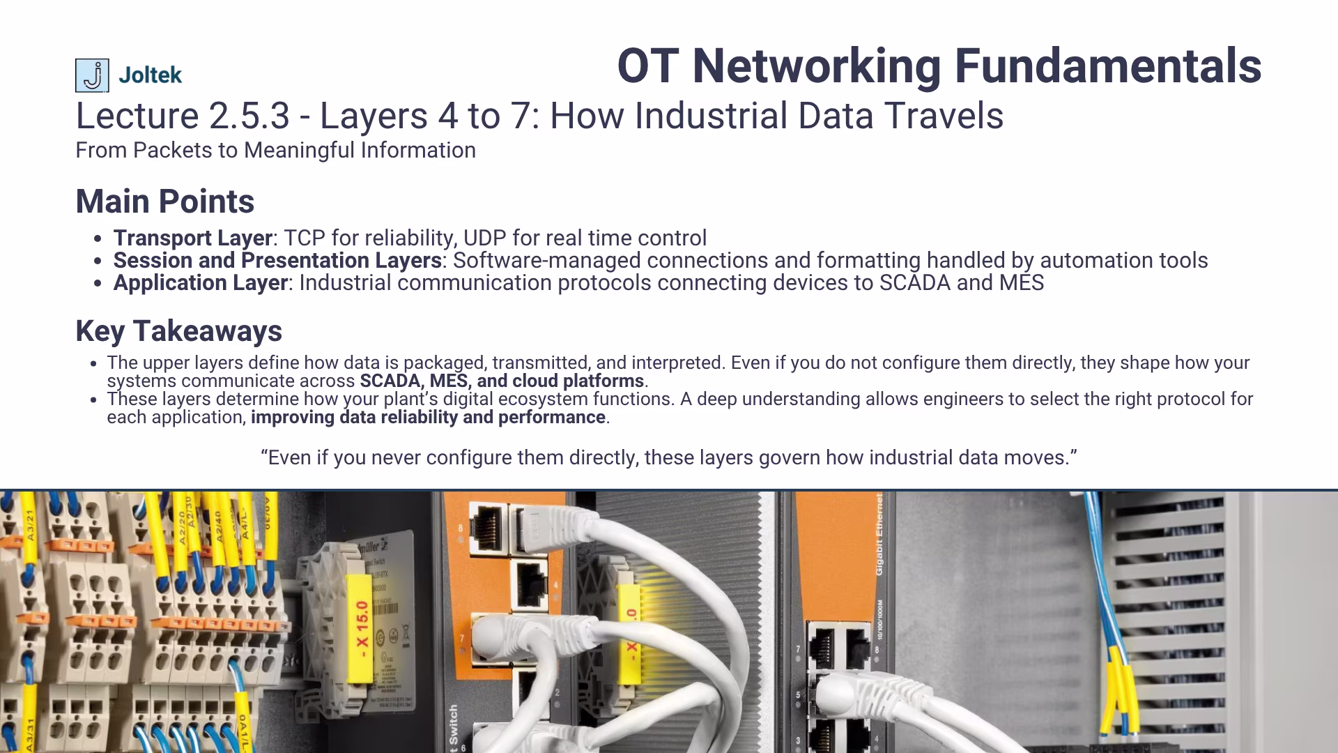
These layers handle the establishment and maintenance of sessions between devices. They manage how conversations start, stay active, and end once data exchange is complete. In industrial automation, these functions are usually abstracted by the software platforms themselves.
For example, when you connect to a controller using Rockwell’s RSLinx or Siemens TIA Portal, these platforms automatically handle session creation and data formatting. They ensure that both ends of the connection understand how data is encoded, compressed, and interpreted. This is especially important when dealing with cross platform communication, where devices from different vendors must speak the same language.
Even though engineers rarely configure these layers manually, understanding their existence helps explain certain system behaviors. Connection timeouts, unexpected disconnections, or handshake failures during commissioning can often be traced back to issues at the session or presentation layers. Knowing how these layers operate makes troubleshooting more methodical and less reactive.
At the top of the OSI model is the layer most engineers interact with every day. The application layer defines the actual communication protocols that industrial systems use to exchange data. These protocols dictate how tags, variables, and commands move between devices, SCADA software, MES platforms, and cloud systems.
In manufacturing, three main protocols dominate this layer:
Each protocol structures and transmits data in its own way, but their goal remains the same: to ensure that operational data flows seamlessly between hardware and software. A proper understanding of these protocols is vital when designing mixed environments, integrating third party equipment, or expanding existing systems.
When engineers understand how these application layer protocols function, they can optimize system performance, enhance data visibility, and plan integration projects with greater confidence. These layers may not be visible to the naked eye, but they form the logical foundation upon which the entire plant’s communication relies.
In today’s connected manufacturing environments, the boundary between information technology and operational technology is thinner than ever. As systems grow more integrated, teams that once operated in isolation are now forced to collaborate on shared infrastructure, shared networks, and shared data. Yet many of the most persistent communication problems do not arise from technology itself, but from misaligned vocabulary and context. Speaking the same networking language bridges IT and OT collaboration.
When an IT engineer refers to a layer three problem, they are often thinking about routing tables, subnets, or firewall rules. Meanwhile, an OT technician hearing the same phrase might start checking a cable or a device configuration at the physical layer. Both are trying to fix the same issue, but they are approaching it from entirely different perspectives. The OSI model provides a universal framework that helps both sides describe issues precisely. Once everyone uses the same terminology, troubleshooting becomes faster, projects move more efficiently, and finger pointing gives way to structured problem solving.
The value of this shared understanding extends far beyond resolving incidents. It also forms the foundation for designing scalable and secure architectures. When IT and OT teams agree on which layers they own, they can set clear boundaries for responsibilities and avoid configuration overlap. IT can focus on routing, segmentation, and security policies, while OT ensures that physical connectivity, device configurations, and automation protocols function as expected. This collaboration is not optional in modern plants. It is the only way to maintain reliable, safe, and future ready operations.
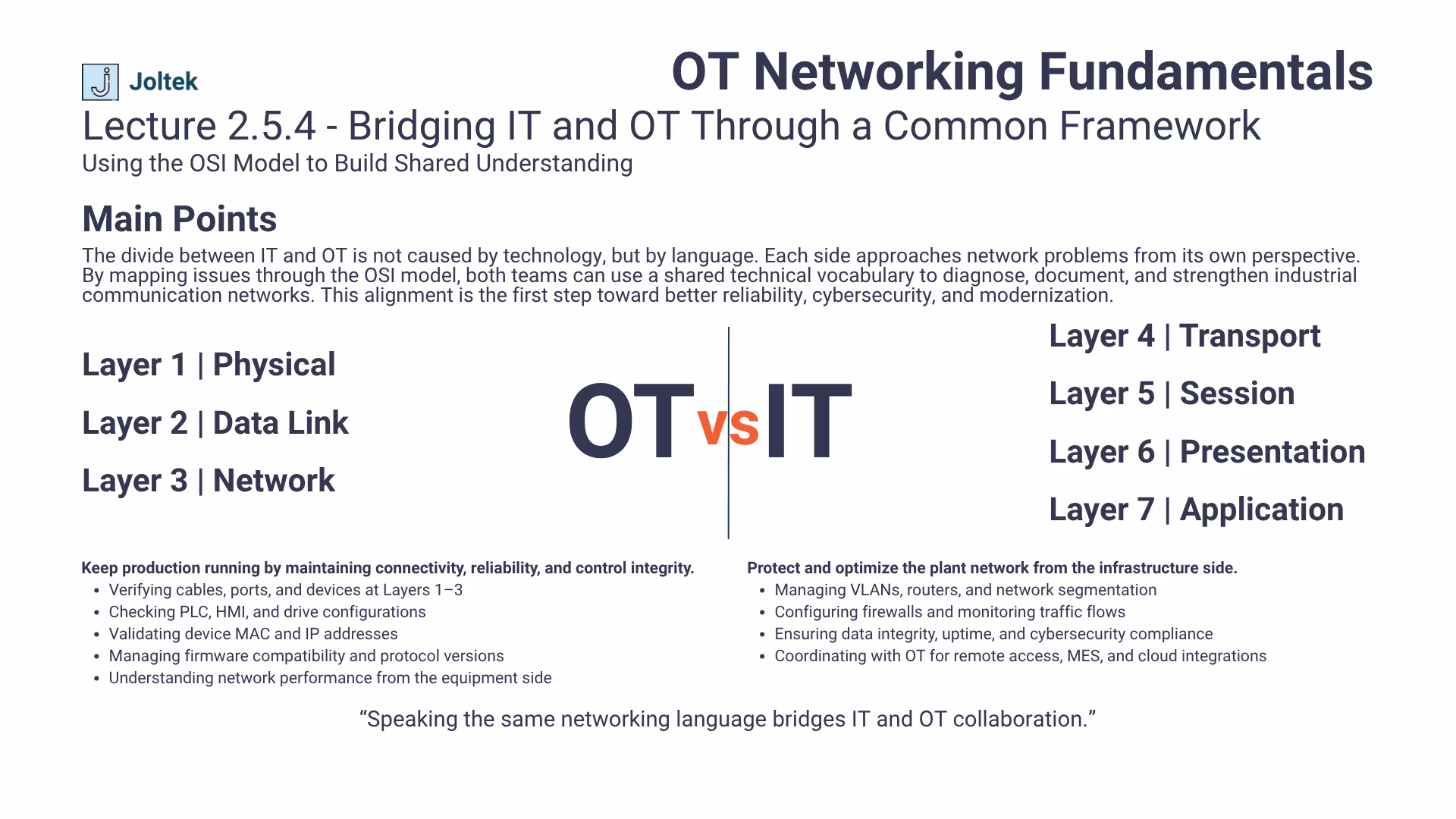
Consider a SCADA system deployment in a large facility. The OT team may handle the configuration of PLCs, HMIs, and IP addresses for each production cell. At the same time, the IT department establishes VLANs, routing rules, and firewall settings that ensure secure data flow between the plant floor and the higher level MES and ERP systems. Both teams depend on each other’s work. A single misalignment between their configurations could lead to communication failures or security vulnerabilities.
This is where documentation, visibility, and shared frameworks become essential. Clear network diagrams, consistent labeling, and unified naming conventions allow IT and OT to see the entire communication flow rather than just their respective portions. When done properly, this collaboration improves not only uptime but also the plant’s cybersecurity posture, since both sides understand how data travels and where vulnerabilities may exist.
For organizations seeking a structured approach to align IT and OT collaboration, the Plant Systems Health Assessment outlines how visibility, architecture mapping, and system documentation help teams identify risks and modernize their facilities effectively.
Understanding the OSI model is not about memorizing technical terms or recalling which layer comes next. It is about recognizing how these layers show up in the reality of a manufacturing environment. Every time a PLC stops communicating with an HMI or a data point fails to reach a SCADA system, the OSI model provides a structured way to trace the problem from the ground up. The model transforms troubleshooting from guesswork into a logical and repeatable process.
When something goes wrong, start at the foundation. Verify that cables are intact, switches are powered, and connectors are properly seated. Then move upward through each layer, confirming device configurations, checking addresses, and validating software communication. This disciplined progression ensures that small issues are not mistaken for complex failures. It also allows teams to communicate more effectively with each other, since they can describe exactly where the problem lies rather than relying on assumptions or vague explanations.
The OSI model also serves as a bridge between engineering and IT, giving both sides a common reference point when diagnosing or designing systems. Whether you are configuring a new controller, setting up an edge device, or deploying a data platform, these layers underpin every part of your network. Developing fluency in this model builds confidence and consistency in decision making across all levels of automation.
The key is simple yet powerful: start from the bottom, verify the basics, and build your understanding upward. A solid grasp of these concepts allows engineers and technicians to see connections others might miss and to approach every system with clarity and precision. It is one of the most valuable skills that any professional working on the plant floor can develop, forming the foundation for effective troubleshooting, smarter design, and stronger collaboration across teams.

